Yttrium Insights Part 4: Core Components
To ensure we understand the same thing when talking about signals, ports and architectures in the yttrium context, I try to give a short high-level introduction in this article.
Mathematical Expressions in Yttrium
In a classical computer algebra system (CAS), expressions are organized in trees. For example, the infix expression A*(B+2) is represented as a tree with * as root element and children A and B+2, where the second child is represented as a subtree with + as root and B and 2 as children. In a simple case, all the leafs of the tree are symbols (variables and numbers) and the other non-leaf nodes define arithmetic operations on their children. Evaluating such a tree is simple: For every operation you first evaluate its children and then execute it on the actual child values, in a recursive way.
Yttrium replaces those trees with graphs. There's no root node anymore, all nodes are equal. Nodes are stateful, so they always have and know their value, you don't have to walk through the whole tree to evaluate its current value. Instead, if a value is changed, it automatically propagates through the graph. Therefore yttrium uses a push model for evaluation, instead of a pull model like classic CAS. In yttrium, these nodes are called Signals; the graph is called a System. Instead of expression manipulation, yttrium is all about system manipulation and simulation. Of course, an algebraic tree-like expression may be represented as a system, too.
From Signals to a System
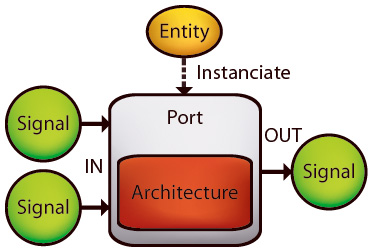
A signal may have a value and various properties and constraints, but does not have any information about operations and relations to other signals. Instead, signals are connected by Ports. A port maintains a set of input and output signals, and a set of buses.
While signals may drive lots of ports (may be connected to more than one port input), a signal may be driven by at most one port only (connected to at most one port output). Buses on the other hand are bidirectional and may be attached to as many ports as needed.
What kind of operation or relation a port stands for is defined by its Entity, a contract specifying the port interface (number of input and output signals, and attached buses) and its symbol and type (e.g. '+' & Std.Add, or 'sin' & Std.Sine).
Evaluation and Architectures
However, neither port nor entity actually implement those operations for simulation. That's where Architectures come in. Architectures are type-specific evaluation implementations of operations and responsible for propagating values from signal to signal. Note that you don't need architectures to manipulate a system with operations like derivation, integration or simplification, because those operations are defined for entities, not architectures.
Ports load architectures dynamically. For example, there is only one addition entity, Std.Add. But you may want to add not only real numbers but also matrices and your own data types. If all the input signals of a port with the Std.Add entity are real-valued, the port will load an architecture capable of adding real numbers. But if you decide to push matrices instead, the port will look for an architecture capable of adding matrices. Ports may replace their architecture from time to time!
Notes about the naming
Some of you may have noticed that the naming is quite similar to VHDL (btw, there are also processes in yttrium, just like VHDL processes). It's not only the naming: the simulation scheduler should be able to simulate whole VHDL models, too. However, there are some important differences, so you better not relay too much on your VHDL experience when working with yttrium.
If you speak German, you may also checkout another more detailed article on the yttrium website.
Update
There's no need for buses here, just use '=' as an operator as you would use it in the next best CAS like maple.
- A) Math.NET
C <= A*(B+2);== MapleC := A*(B+2); - B) Math.NET
A*(B+2) = C;== MapleA*(B+2) = C;
A is a simple assignment, while B is an equation (that could be assigned to a variable/signal if needed). Your example with two '=' could easily be modeled with three input signals to the '='-port, one for each term:
1: 2: 3: 4: |
|
Of course you need algorithms to symbolically solve those equations if e.g. only A and C are known but not B.
I think I see what you're up to. Theoretically we could work with Buses and something like Factor Graphs - is this what you have in mind? You don't want to build explicit equations at all, just model a system. Such a system contains loads of implicit equations (automatically), which could hopefully be solved with simpler and more local algorithms (Factor Graph like). Does this come close?